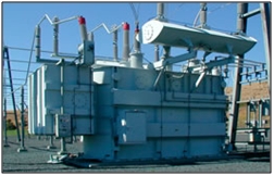
In this article we will learn about how to do transformer protection.
What we can prepare steps for transformer protection. We will discuss about the
electrical device which is useful in transformer protection.
Transformer protection
Fault in the transformer is of following when drawn on a
graph.
Fault in Auxiliary Equipment’s
The following can be considered as auxiliary equipment’s of
the transformer.
1. Transformer
2. Gas cushion
3. Oil pumps and forced air fans
4. Core and winding insulation
Winding fault
There may be faults between adjacent turns or parts of coils
such as phase to phase faults another fault may be fault to ground or across
complete winding such as phase to earth faults on the HV and LV external
terminals.
Over-loads and external short circuits
Over-loads may be sustained for long periods, being limited
only by the permitted temperature rise in the winding and the cooling medium.
Excessive overloading will result in deterioration of insulation and subsequent
failure.
Differential protection of transformer
Differential transformer protection is the most important
type of protection used for internal phase to phase and phase to earth faults
and generally applied to transformer having rating of 5MVA and above. The
differential protection of transformer is also known as merz-price protection
for the transformer. A schematic diagram of differential transformer protection
scheme for a star- delta power transformer shown in below fig.
In a star delta transformer, the load currents in the two
winding are not in direct phase opposition but are displaced by 30 degree and
to allow for this the CT secondary are connected in delta on the star side and
in star on delta side.
Gas Actuated Rely-Buchholz Relay
The heat produced by internal fault or overloading of
transformer oil to decompose and produce a gas which can be made to detect the
winding fault. Buchholz relay is an electrical device which use to transformer
protection form heating of winding.
Buchholz relay is a simplest form which is used in all transformers
produced with conservator.
Bus-Bar Arrangements
Bus-bar are arranged to achieve
1. Adequate operating flexibility
2. Sufficient reliability
3. Minimum Cost
The cost can be minimized by reduced the number of circuit
breakers to a minimum but complication of the protective gear are increased.
Some bus bar Arrangement
It is also main step in transformer protection.
In this arrangement a set of bus-bars is used for complete
power station and to this bus bar are are connected all generators. Transformers
and feeders through circuit breakers and isolating switches. Such a bus-bar
arrangement is cheaper in initial as well as in maintenance cost and simple in
operation and relaying.
Single Bus-bar system with sectionalisation
With increased number of generators and outgoing feeders
connected to the bus-bars, it becomes essential to provide arrangement for sectionalizing
the bus bars so that a fault on any one section of the bus-bars may not cause a
complete shutdown. This is achieved by providing a circuit breaker and
isolating switches between the sections. This is main step of transformer
protection because bus bar proper arrangement is more important than other.
Ring bus-bar system
In this arrangement each feeder is supplied from two paths,
so that in case of failure of a section, supply is not interrupted.
Double main and transfer bus bar Arrangement
Double main and transfer
bus bar arrangement is also important for transformer protection. This arrangement
incorporates all advantages of the double bus as well as transfer bus-scheme. The
scheme needs a bus-coupler for the on load transfer to circuits from one main
bus to the other and a transfer coupler for taking out circuit breaker of various
circuits for maintenance. Double main and transfer bus bar arrangement is also important for transformer protection.
hence it is transformer protection if you will find any incorrect above please comment below in comment box.
For more about transformer protection you must watch this video.
hence it is transformer protection if you will find any incorrect above please comment below in comment box.
For more about transformer protection you must watch this video.


